4. Making an Electric Machine using eMach
Goal: Code and execute script to make an SPM machine using
mach_cadmodule withineMachComplexity 2/5
Estimated Time 15 min
This tutorial demonstrates how to draw / build an SPM machine using the tools supported by eMach. By the end of this
tutorial you will be able to:
use
mach_cadclasses to define 3D componentsdraw 3D components in any
eMachsupported tool of your choice
4.1. Requirements
All required Python packages are installed on system (see Pre-requisites)
Installation of any one of the tools supported by
eMach(eg: JMAG, MAGNET)Personal repo using
eMachas submodule established (see Rectangle Tutorial)
4.2. Step 1: Create script file with required module imports
In the root folder of your repository, create a Python file named draw_spm.py. All the code used in this example will be
written in this file. At the top of draw_spm.py add the following import statements:
from eMach.mach_cad.tools import jmag as jd
from eMach.mach_cad import model_obj as mo
These imports give the user access to capabilites offered by mach_cad, in particular the JMAG-Python interface tool and the
model_obj classes which contain the smarts to draw different types of geometries commonly found in electric machines using
certain parameter inputs.
4.3. Step 2: Create required mach_cad cross-sections
In this step the user will create the different cross-sections required to define an inner rotor surface permanent magnet machine.
This includes cross-sections defining the stator iron, permanent magnets, and rotor back iron. An overview of the cross-sections
supported by eMach is provided here.
These cross-sects vary greatly with regards to their degree of complexity from basic rectangles, to more involved geometries such as the stator of a
linear motor. The stator of the machine in this tutorial uses the CrossSectInnerRotorStator class.
The below example code creates an inner rotor stator cross-section object which can be used subsequently for creating the component
in 3D.
# define stator cross-section
stator1 = mo.CrossSectInnerRotorStator(
    name="stator",
    dim_alpha_st=mo.DimDegree(44.5),
    dim_alpha_so=mo.DimDegree((44.5 / 2)),
    dim_r_si=mo.DimMillimeter(14.16),
    dim_d_sy=mo.DimMillimeter(13.54),
    dim_d_st=mo.DimMillimeter(16.94),
    dim_d_sp=mo.DimMillimeter(8.14),
    dim_d_so=mo.DimMillimeter(5.43),
    dim_w_st=mo.DimMillimeter(9.1),
    dim_r_st=mo.DimMillimeter(0),
    dim_r_sf=mo.DimMillimeter(0),
    dim_r_sb=mo.DimMillimeter(0),
    Q=6,
    location=mo.Location2D(anchor_xy=[mo.DimMillimeter(0), mo.DimMillimeter(0)]),
    theta=mo.DimDegree(0),
)
Each of the arguments provided in the above class definition corresponds directly to a geometric parameter of the inner rotor stator.
To know what these arguments correspond to users can navigate to the folder in which the implementation of each cross-section resides.
Here, a README.md file and a .svg file describing each parameter is provided. This makes it convenient to view the geometry within GitHub.
The link to the inner rotor stator folder is provided here.
Please navigate to this link to get a better understanding of what each argument provided for the CrossSectInnerRotorStator.
All cross-sections also include the additional arguments of location and theta. This is used to define the
displacement of the cross-section from the global origin (x=0, y=0, theta=0). Users are encouraged to review the
eMach cross-sections specifications document.
Another key feature of eMach is its capability to handle different dimensions. In
order to ensure that the dimensions expected by the user are respected across different platforms, eMach defines its own
classes for linear and angular dimensions. In this particular
example, we have used DimMillimeter to describe linear dimensions in mm and DimDegree to describe angular dimensions in
degrees. The complete set of eMach dimensions can be found here.
Similar to creating the CrossSectInnerRotorStator object, users are recommended to try creating other cross-sections objects
required for creating the SPM machine. This includes using the CrossSectArc for the magnets, and the CrossSectInnerNotchedRotor
for the rotor. The dimensions can be specified according to the users whim, so long as the outer radius of the arc magnets are
smaller than the inner radius of the stator bore, and the outer radius of the inner notched rotor is equal to the inner radius of
the arc magnets. Users can create any multiple of two arc magnets in their SPM machine.
Note
In case you have trouble with this example, refer to the script example_spm.py for a working example of drawing a 4 pole, 6 slot surface permanent magnet machine in JMAG.
4.4. Step 3: Create Components from CrossSects
In the previous step, all information associated with the 2D geometry of each machine component was defined. To convert these
cross-sections to components, we need to define 1) the material defining the component and 2) a method by which the 2D cross-section
should be converted to a 3D component. For materials, eMach uses just a wrapper class with a name field. In the present
implementation, this name directly corresponds to the name of materials existing by default in the FEA tool and the code simply
assigns this material to the cross-section within the tool. For converting the cross-section to a 3D component, eMach currently
support 2 methods: extrude and revolve. Extrude, as the name implies, sets a height to the cross-section and extrudes it in a
direction normal to the cross-section plane. Revolve rotates a cross-section about an axis and a center through a certain angle to
get a 3D component. In most applications, users will primarily be using the extrude feature.
The below code snippet shows how to create a component from a cross-section within eMach. In this particular example, the stator
has been assigned a standard electric steel material supported by JMAG, 10JNEX900, and has been extruded to a length of 25mm with
the make_solid=mo.MakeExtrude(location=mo.Location3D(), dim_depth=mo.DimMillimeter(25)) argument. Following a similar procedure,
components can be made for the remaining cross-sections as well. Users are recommended to use 10JNEX900 and Arnold/Reversible/N40H
materials for the rotor back iron and magnets respectively. All cross-sections should be extruded to the same height (25 mm in this case).
stator_comp = mo.Component(
    name="Stator",
    cross_sections=[stator1],
    material=mo.MaterialGeneric(name="10JNEX900", color=r"#808080"),
    make_solid=mo.MakeExtrude(location=mo.Location3D(), dim_depth=mo.DimMillimeter(25)),
    )

# add code below for remaining components
4.5. Step 4: Make Components
After step 3, all the information required to make components in any eMach tool is available. The final step of actually making
these components is achieved using the below classes / function calls. Again the code below shows the implementation for the
stator component alone.
# create an instance of the JMAG class
tool_jmag = jd.JmagDesigner()

# create a new JMAG file and study
file = r"full_SPM_trial.jproj"
tool_jmag.open(comp_filepath=file, study_type="Transient")

# make stator component
stator1_handle = stator_comp.make(tool_jmag, tool_jmag)

# add code below to make remaining components
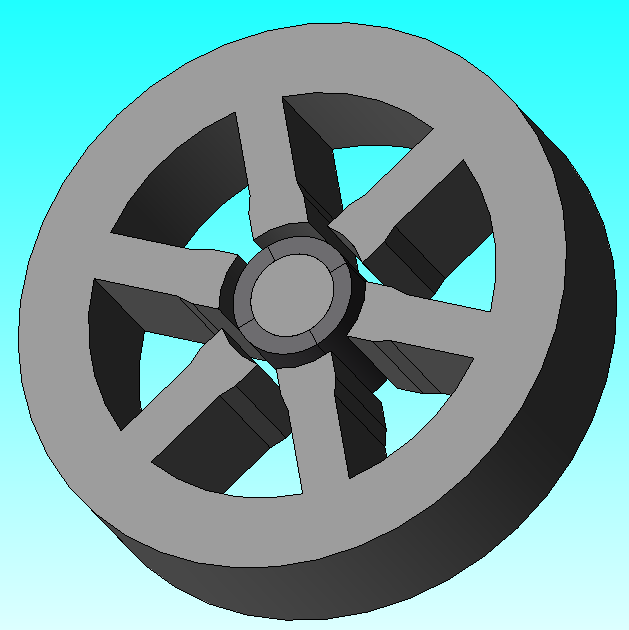
Upon running the above script, an instance of the JMAG application should be launched on your PC and the corresponding components should be drawn in the sequence they were defined in. The end result is expected to look as shown in the figure below.
4.6. Conclusion
Congratulations! You have successfully used eMach to make most of the components required to simulate a surface permanent
magnet machine! Users are recommended to further explore additional cross-sections currently supported by eMach or to create
their own cross-sections which they feel are generic enough to find use in a wide range of electric machine applications.
If it takes a considerable amount of time to draw a motor in JMAG using the above approach,
users are suggested to have a look at another approach, as demonstrated in eMach/examples/mach_cad_examples/example_induction_motor_jmag.py
for an example induction machine. In this example, all cross-sections are first drawn in
JMAG Geometry Editor and only then exported to JMAG Designer.